 |
Application Note
Adjustment of the Opto Sensor in the
ST-5C and ST-237 Cameras
May 3, 2000
This application note describes how to locate and adjust the opto sensor that controls the positioning of the shutter wheel and internal filter wheel (CFW5C) in the ST-5C and ST-237 cameras.
Adjustment of the opto sensor may be necessary when replacing the shutter wheel with the optional internal filter wheel or anytime the shutter wheel or filter wheel do not correctly position their openings over the CCD. This adjustment should only be attempted if your filter wheel does not position itself properly when directed to do so by CCDOPS, e.g.: spinning and not finding the right filter, skipping a filter or finding the wrong filter. There are two solutions and somtimes both are necessary to fix the problem:
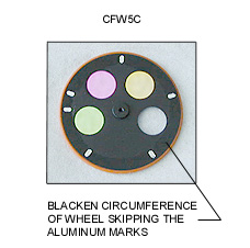
(1) The opto sensor works by detecting the contrast between the black surface of the filter wheel and the bright aluminum marks that are scribed on the underside. We have found that by using a flat black marker we can carefully paint the black surface of the filter wheel surrounding the bright aluminum marks and increase the contrast because the black annodized surface reflects IR. By painting a ring around the circumference of the underside of the wheel (skipping the bright aluminum marks) we reduce the IR reflectivity of the dark area and increase the contrast seen by the opto sensor. It is only necessary to paint a stripe around the wheel about the same width as the bright marks, being careful to avoid the o-ring, the filters and the aluminum marks.
|
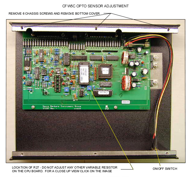
(2) If this isn't enough, the voltage to the opto sensor can be adjusted slightly to fix the problem. Because the adjustment is very sensitive we have done this in the past only here at SBIG but it is not too difficult to do in the field if you are careful. The opto sensor is very sensitive and normally only a small adjustment of a variable resistor (R27) located on the CPU board is necessary for correct functioning. The location is variable resistor R27 is shown in the photographs below. The photos show the CPU board of an ST-237 camera. The location of R27 is the same on an ST-5C CPU board. Remove the 6 chassis screws that attach the bottom cover. The CPU board is attached to the inside of the top cover. Locate R27. Depending on the model of camera and board version there may be several variable resistors that look the same as R27. It is important that you do not adjust any other resistor except the one marked R27. Before you make any adjustments, note the starting position of the adjustment screw of R27.
Turn the pot 1/8th turn in either direction and test the functioning of the filter wheel or shutter. If it is not working properly turn the pot 1/4 turn in the opposite direction (e.g., 1/8th turn past the starting position in the opposite direction) and test it again. If this still does not result in correct functioning of the shutter/filter wheel, try 1/4 turn in either direction instead of 1/8th turn from the starting position.
The photo below shows the whole view of the CPU board attached to the inside of the top chassis cover. For a close up view of the CPU board and the location of R27 click on the photo below.
 |
Revised: May 05, 2000 10:35:22 AM.
Copyright © 1998 Santa Barbara Instrument Group, Inc. All rights reserved.
Please report any problems with this page directly to the Webmaster