SBIG Fiber Optic Field Positioner
December 11,2008
$1495 (ST-402ME Camera sold separately)
 |
|
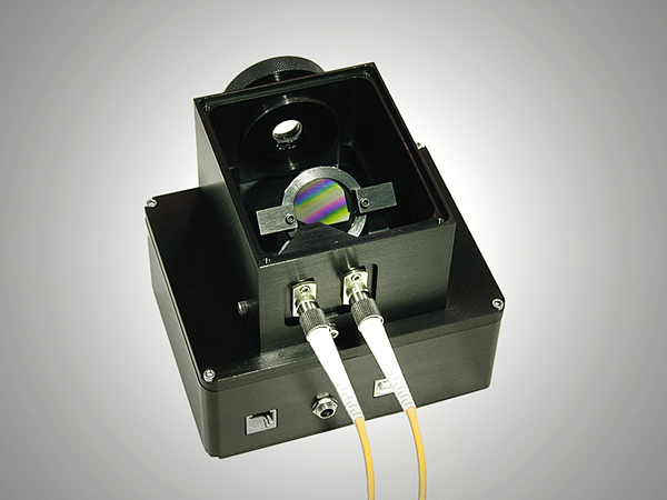
Fiber Optic Field Positioner (top) attached to and ST-402ME CCD Camera |
|
|
|
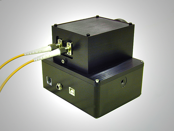
Fiber Optic Field Positioner (top) attached to and ST-402ME CCD Camera |
Overview: SBIG has two spectrograph models currently available to users – the DSS-7 and the SGS. To achieve spectral resolutions higher than that available with these models requires physically larger units than comfortably fit on the back of an amateur sized telescope, and also requires temperature and mechanical stability incompatible with a lightweight unit. To support spectroscopy at these higher resolutions SBIG has developed the Fiber Optic Field Positioner (FOFP), an accessory for the ST-402 that allows a star’s energy to be efficiently focused onto and injected into a fiber tip as small as 50 microns (0.002 inch) diameter. This solves a difficult problem associated with the use of fiber optics in astronomy. Typically a user might have to flood the fiber tip to collect the light, which is very inefficient for point sources, or have to hunt for the fiber tip and peak up the energy, a frustratingly slow process. Our new Fiber Optic Field Positioner solves this problem, and opens up a new arena of fiber-based instrumentation.
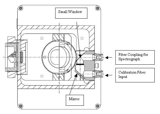
Description: The design of the positioner is illustrated in Figure One. 8% of the light entering the unit is reflected to the ST-402 CCD by a pellicle beam splitter, and the rest passes through toward the fiber. The ST-402 shows the star field and allows the unit to be precisely focused and positioned on the sky. The star which is the desired target is positioned to a specific pixel location, at which point the bulk of the energy is entering the fiber. This is all very straightforward. The trick is determining which pixel corresponds to the fiber tip, and making the fiber tip coplanar with the CCD.
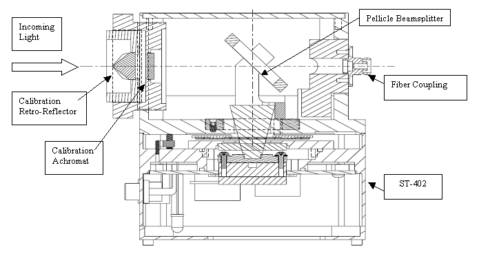
This is done using the calibration items
(also shown in Figure One), which are only used to locate the fiber tip, and are
removed in normal use. The unit is taken off the telescope and a small
achromatic lens screwed into the T-thread coupling on the FOFP. The unit
is then pointed at a remote streetlight, star or scene and the user focuses the
scene on the CCD by rotating the T-thread coupling. A star field at good
focus is illustrated in Figure Three. Once best focus is determined, the
retro-reflecting corner cube is attached in front of the achromatic lens, and
the output end of the fiber tip illuminated by pointing it at a bright scene
(light is sent BACKWARDS through the fiber). The The light that exits the fiber tip
is collimated by the achromat lens and retro-reflected right back to the fiber
tip by the corner cube. Of course, 8% of the light goes to the ST-402, allowing
the tip to be focused and its position determined. The image will look as
illustrated in Figure Three. This is the trick that makes this all work. After
focusing the tip and determining the target pixel the retro-reflector and lens
are removed. The tip is focused by moving the block carrying the fiber couplers
back and forth.
Note: in Figure Three the image on the left shows three spots. The brightest one is the fiber tip reflected back by the retro-reflector. The faint image above it is from the thin window above the fiber tip. The fairly bright spot on the left side is the reflection from the flat face of the retro-reflector. This reflection moves when the retro-reflector is rotated or manipulated, and can be eliminated by tilting the retro-reflector about 5 degrees, as shown on the right side of Figure Three. One should focus the bright image.
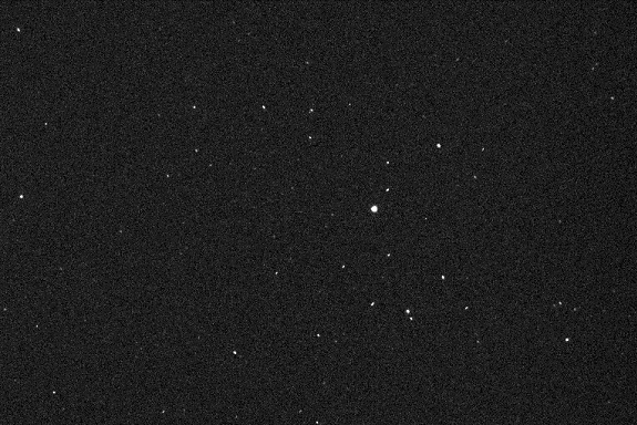
Figure Two: Star Field captured with Fiber Optic Field Positioner with the Calibration Lens Attached. The image quality is quite good.
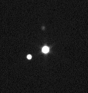

Figure Three: Retro-Reflector Image of Fiber Tip
While some users might be concerned that only 8% of the light goes to the ST-402, a little experience with spectroscopy will make it apparent that any star that is a target for high resolution spectroscopy will be easy to guide on. For example, at one angstrom per pixel resolution the star will be smeared out over 4000 to 5000 pixels width, and about 5 pixels tall, or around 25000 pixels. The spectrograph efficiency will be around 50%. The ST-402 is guiding on 8% of the starlight, but the light is concentrated on about 25 pixels, and will be 250 times brighter.
A second fiber path, shown in Figure Four is for calibration light. A spectral line source can be injected into the main fiber while the spectrum is being collected without interfering with the guider. While this light does not exactly match the main telescope’s F/number and spot size energy distribution, it will still provide comparison lines during the exposure to monitor spectrograph alignment. A better way would be to illuminate a white screen in front of the telescope aperture that is floodlit by a spectral comparison lamp, but that cannot happen during the exposure. Users not needing this feature can remove the small window in front of the fiber tip to gain back 10% more sensitivity. In practice one should develop a spectral offset measure between the calibration fiber and the better illumination method of flooding the white screen. Of course, for a star there is an error that can occur if the star does not uniformly illuminate the fiber tip, which it will probably not. The use of the FOFP can make the star positioning on the fiber more repeatable, minimizing this error.
Note: the fiber connector provided is the popular FC connector. The user is recommended to buy pre-fabricated multi-mode fiber optic patchcords with 50 or 62.5 micron core diameters. A 0.12 NA (numerical aperture) version is fine, but 0.22 NA works also. Edmund sells such patchcords in short lengths. Thorlabs is another choice. Many companies on the web sell patchcords. Avoid single mode fiber since it has a quite small core diameter. The attenuation of light in 5 meters lengths with multimode fiber is acceptable from 400 to 900 nm.
|
|
Revised:
December 11, 2008 01:51:47 PM.
Copyright © 2008 Santa Barbara Instrument Group, Inc. All rights reserved.
Please report any problems with this page directly to the Webmaster