|
TELRAD SIGHT PULSER
an add-on blinking circuit for the Telrad sight

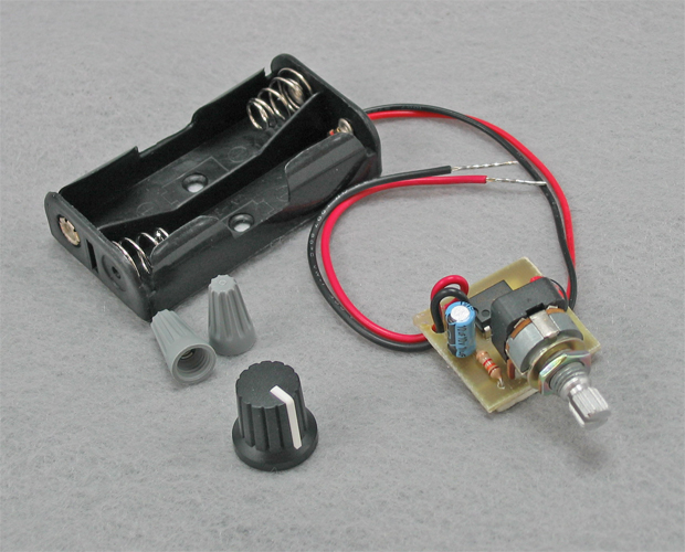
Above: Pulser kit potentiometer and circuit board assembly with "AA" Battery Holder, Dial, Wire Nuts (95,411 bytes).
Click on image to see enlarged view (210,656 bytes).
 The reticle illumination source of the Telrad sight is a red Light Emitting Diode (LED) powered by two "AA" batteries. The LED is controlled by means of a potentiometer at the right rear corner of the Telrad, rotating the dial varies the intensity of the LED. While this arrangement permits the observer to adjust the brightness of the light source, this is either a continuous on or off arrangement.
Left: Telrad Sight Reticle Pattern - display set to near maximum brightness to show up better in photograph.
Over time, some observers noted that by "blinking" the faint red pattern of a sight or guiding eyepiece this made it easier and less fatiguing to observe the very faint objects in the background. Some developed "blinking" circuits to turn the light sources of their sights on and off automatically, with more sophisticated versions permitting the operator to vary the period of time between the on blinks. When the Pulse control is dialed to "on" then the reticle pattern alternates on and off repeatedly with a frequency that can be controlled by turning the dial. In response to suggestions Company Seven offers the Telrad Pulser as an accessory for the Telrad sight which may be installed by the user.
The only tools needed for installation of the Telrad Pulser are two drill bits of 5/16 and 5/64 inch (8 and 2 mm) diameter.
Installation of the Telrad Pulser:
Slide forward and remove the Telrad battery access cover.
Remove the battery holder, then remove both batteries.
Cut the battery holder wires cutting each at a point closest to the battery holder terminals. Then strip about 3/8 inch (1 cm) of insulation from the ends of the two wires.
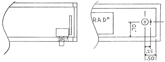
Drill two holes into the Telrad housing as illustrated in the template shown below:

Above: Drawings of Pulser installation in forward right wall; dimensions are in inches.
At left is installation as viewed from above the sight, and at right as seen from the side of the Telrad. (18,786 bytes).
Click on image to see enlarged view (29,787 bytes).
Remove the nut and washer from the Telrad potentiometer, position the wires on the ides of the Pulser assembly and feed the shaft through the larger hole. Line up the locating lug in line with the smaller hole.
Slip the washer and then the nut over the potentiometer shaft and thread the nut in place. Tighten this only until the potentiometer is snug against the inside surface of the Telrad case but to avoid stripping the threads do not over tighten.
Splice the open ended wire leads of the removed battery holder onto the wires from the potentiometer: splice red to red and black to black. You may use the provided wire nuts, or solder the connections. For added reassurance these connections may be wrapped with electrical tape.
Push the spliced wires into the Telrad housing in a manner so that they do not interfere with installation of the battery holder.
install fresh batteries into the holding noting the correct polarity embossed in each battery space. Install the battery holder into the Telrad being careful to avoid the Reticle Housing, the spliced wires, or the potentiometer circuit board.
Slide the battery access cover into place. Slip the black knob onto the potentiometer shaft, orienting the reference mark to your preference.
Your Pulser is ready for use!
Operation of the Telrad Pulser:
Your new Pulser is easy to use, the original control will still regulate the brightness of the reticle pattern while the Pulser controls the pulsing on and off.
The Pulser potentiometer switch turns the power to the instrument on and off. And so to avoid draining the batteries you should leave this off when the Telrad is not in use.
Turn the Pulser control dial clockwise fully then to control dial it back gradually to attain the desired pulse interval.
To switch off, turn the Pulser control fully counter clockwise until you feel the click.
The Pulser operates on a 50% duty factor between 0.8 Hz and something faster than 60 Hz and so it appears to be constantly on. The Pulser acts as a switching power supply so it also prolongs battery life. It is engineered and made consistently well in the U.S.A.
TELRAD PULSER SPECIFICATIONS
| SPECIFICATIONS |
| Pulse Frequency: |
5/16 and 5/64 inch (8 and 2 mm) |
| Switching Power Supply: |
50% Duty Cycle |
| Installation Tools required: |
5/16 and 5/64 inch (8 and 2 mm) |
| Pulser weight: |
0.7 ounces / 20 g |
* Specifications are subject to change without notice.
|