
|
C-7 Home Page |
|
|
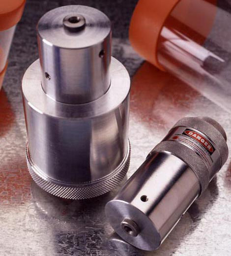
Above: Glatter Laser Collimators - combination 1.25/2 and 1.25 inch models (33,462 bytes). Click on the above image to view enlargement (87,659 bytes) HOWIE GLATTER LASER COLLIMATORS
The laser collimator is a tool which enables precise adjustment of the position and alignment of telescope optics, so as to obtain the best possible image contrast and resolution. Inside is a solid-state laser diode, which emits an intense laser beam exactly along the central axis of the cylindrical collimator body. The beam acts as a "reference line" from which alignments are made. CAUTION: The lasers in the Glatter collimators are are class IIIa lasers with a maximum output of 5 thousandths of a Watt. These are quite safe if they are used with reasonable precautions. Direct or mirror-reflected eye exposure should be avoided! Information reviewed in electro-optic industry trade magazines suggests that for detectable damage to the eye to occur, the laser beam must stay focused on the same area of the retina for at least 0.25 second. Therefore, one must be careful when collimating to ensure that the beam does not enter anyone's eye. There is no danger in viewing the beam impact on a surface that produces a diffuse reflection, such as that on the face of the laser collimator. The beam impact may also be safely viewed on a mirror or lens surface, if the reflected or transmitted beam is not directed towards your eye. All precautions should still be followed to avoid the beam entering anyone's eye! A badly miscollimated Newtonian or Cassegrain may allow the beam to exit the front of the telescope, so when collimating, check first by pointing the telescope at a wall or screen to see if the beam is getting out. With a refractor, the beam will always exit the front of the telescope, so run a strip of masking tape across the diameter of the dew cap opening as a safety beam stop. There is some ambivalence among some amateur astronomers regarding the use of portable laser collimators, because they believe it is good for the novice to learn how to adjust the mirrors by just looking through the eyepiece holder. This practice develops familiarity with the optical system. These amateur astronomers share an opinion that providing a laser collimator to a novice is like giving pocket calculators to kids who should be studying multiplication tables. Howie Glatter realized that collimating with a laser can provide as much insight into optical alignment as collimating by eye through the eyepiece holder; "when applied correctly, the darned thing was so accurate and quick that I couldn't resist it. The fact that collimation could be done in the dark with ease also seemed like a great advantage. Since I was making them myself, I felt I could produce a very high quality collimator at a reasonable price, and put more of them into people's hands (I love machining stuff anyhow). It seems to be working out well, and I feel blessed that I can earn a living from something I believe in." Holographic Collimator has in addition to the laser, a removable transparent diffractive optic (the "hologram") that is placed in the path of the beam, just ahead of the laser. It diffracts light from the laser to project a diverging, symmetrical pattern around the beam, which is quite useful for centering optical elements and other procedures. While several holographic patterns are available, the most versatile seems to be a 9 x 9 checkerboard grid of illuminated lines, which is standard with the Glatter holographic collimators. The grid covers a wider angular range (21 degrees) than any other holographic collimator which allows direct centering of f/ 2.7 to f/ 35 optics. A rectilinear grid pattern gives the highest accuracy and sensitivity for centering circular optics of arbitrary size. A "scope", or concentric circle pattern can only be as accurate, if one of it's rings happens to be very near the optic's edge. The diffractors are individually fit to their collimators for maximum alignment accuracy, so be careful not to accidentally or purposely switch diffractors from one device to another. If switched, maximum alignment accuracy in the holographic mode is likely to be lost. There are some collimating situations where the diffracted pattern is unnecessary and maximum power in the central beam is desired, so the diffractor of the Glatter collimator may be unscrewed from the laser aperture, converting the holographic collimator to single beam mode. 532, 635, or 650nm Wavelength? The larger the holographic pattern is, the more the laser's light is spread out, and so the pattern becomes less bright. Glatter offers the red holographic collimators with a choice of either 650 nanometer or 635nm wavelength. The 635nm. lasers appear about two or three times brighter than the 650nm, but these are more costly. The two lasers actually have the same radiometric power output, but the human eye's sensitivity to the shorter wavelength is greater. The difference would be in the level of ambient light that collimation can be done in. The ultimate in pattern brightness is available with the Glatter 532nm green holographic laser collimator. It utilizes a 5 mw, 532nm laser that produces a high intensity green beam. This beam appears much brighter than the red ones in part because the human eye is most sensitive to light in this area of the spectrum. The 532nm beam makes collimation easy even in full daylight. The green collimator can also be used as a pointer for pointing out celestial objects to groups of people. This collimator has a body dimension of 4-1/2 inches in length. This incorporates two nosepiece diameters of 2" and 1-1/4" so that it can fit into either focuser. Laser Accuracy and Stability The most important specifications for a laser collimator are the accuracy and stability of the laser beam alignment to the cylindrical axis of the collimator body. Glatter's alignment tolerance is fifteen arc seconds for single beam mode, and one arc minute for the holographic mode. In order to ensure maintenance of this level of accuracy each of these collimators are tested for resistance to shock. Glatter has designed the collimator bodies to withstand a shock equivalent to dropping the collimator from the eyepiece position on a tall Dobsonian telescope, without alteration of laser alignment. Most other laser collimators cannot withstand this kind of accident without loss of alignment. Principal of Operation In use, the collimator is placed in the telescope eyepiece holder. Conventional collimation, with light coming from the sky end of the telescope does not depend on eye piece holder angular alignment, although it does include it if a thorough job is to be done. Eyepiece axis misalignment is hardly ever noticed by visual observers, because modern eyepiece designs are so good, even with off axis rays. In contrast, since laser collimation proceeds from the eyepiece axis, true alignment of and with that axis is very important. In fact, eyepiece axis alignment problems are the greatest cause of laser collimation difficulties; and so if the eyepiece holder does not provide a stable pointing direction for the collimator, then consistent results cannot be expected. There are two possible components to this misalignment:
2. Instability of pointing direction, as focuser tube travels. Typically with helical focusers the laser spot may be seen to travel in a circle. While with rack and pinion focusers, the spot may be seen to jump back and forth every time focus direction is reversed.
The focuser can be precisely aligned with the main tube using a simple procedure I've developed that utilizes just a single beam collimator. There' s no need to punch holes in the tube or use measuring tapes, but you will need a good carpenter's or framer's square. You also need to temporarily remove the secondary. Briefly, you first check that the tube's front opening is square with the tube axis, then measure back from the tube front edge to the laser beam, projected from the focuser. Make this distance the same on both sides, near and opposite the focuser by tipping the focuser forward and backward. Next, cut a strip of cardboard to span the tube's inside diameter and mark it's center. Place it at right angles to the focuser, and adjust focuser side to side, so that the laser beam hits the mark. It's not absolutely necessary to do this alignment unless the focuser is grossly misaligned, but for optimized performance, it should be done. The holographic collimator allows precise positioning of the secondary mirror on the eyepiece axis without resorting to marking the secondary. The secondary should not be marked because unlike the primary, it's center is in use. The secondary is positioned by moving it to center the projected pattern on it, or by centering the shadow of the diagonal within the grid pattern, projected on the tube wall behind the diagonal. This produces the proper "offset" towards the primary. Next, the angular alignment of the secondary mirror is adjusted so that the beam strikes the center of the primary mirror. With the single beam laser collimator, you will need a dot or "donut" placed on the center of your primary as an aid to precise beam centering. A donut is preferable, as a completely opaque dot will not allow reflection of the beam, preventing primary mirror alignment; however, a dot made with a permanent marker will transmit enough light to allow collimation. Don't worry about putting a dot on your primary: The center is not in use because it's in the shadow of the secondary. The Glatter Laser Collimator package is supplied with self-adhesive collimation "donuts", and instructions for their safe placement. With the holographic collimator, the center dot is not necessary, as you can center the grid pattern on the edges of the mirror. Next, the primary is adjusted so that the beam retraces it's path, and returns to the laser opening in the front surface of the collimator. The returned beam can be seen striking the face of the collimator, and the primary is adjusted to move this spot to the center. The best way to view the returned beam impact on the collimator face is from the front of the 'scope, looking down the tube, by double reflection in the primary and secondary. That way, short (and lightweight) collimators are fine in tall focusers. The primary adjustment can also be done by making the up and down going laser beam's impact points on the secondary coincide. There is an additional method of primary adjustment with the holographic collimator, that takes advantage of the fact that a telescope will work in reverse to turn the diverging rays from the hologram into a parallel beam. The holographic pattern will be projected a great distance from the scope, and will remain constant in size. The primary can be adjusted by observing the pattern projected from the telescope upon a screen or wall, and centering the projected grid pattern in the projected aperture. This procedure facilitates solo collimation. For it to work accurately, you must first align the focuser with the main tube, and center the primary within the tube.
The collimator is placed in the draw tube (straight through; no diagonal prism or mirror used), and the draw tube axis is checked for alignment by seeing if the beam passes through the center of the objective. With a single beam collimator you can cut a paper circle the size of the front cell opening and punch a small hole in it's center to check beam centering. With the holographic collimator the paper is not needed, as the centering of the target pattern can be checked directly. Next adjust the objective so that the beam, which is reflected from the rear surface of the objective, is returned to the collimator face and centered on the laser aperture. Enough light is reflected even from an antireflection coated lens surface to perform this adjustment, although you probably will want to remove the diffractive element if you are using the holographic collimator. The general principle in laser collimating Cassegrains is to first insure the accessory holder/eyepiece back's eyepiece axis coincides with the main tube axis. Then put the secondary, primary, and corrector plate (if present) successively into alignment with that axis. The single beam collimator will take you as far as eyepiece axis and secondary mirror alignment, but the holographic collimator is necessary for primary and corrector alignment. First, the back fitting should be checked for centrality with the main tube by measuring all around with a ruler or caliper. Next, the secondary should be similarly checked for centrality. Then the alignment of the back's axis can be checked by placing the collimator in the eyepiece holder (no diagonal mirror or prism used), and checking that the laser beam strikes the center of the secondary. The alignment of the back axis within the main tube can also be checked by measurement with with a cardboard strip, marked at it's center, as was done in Newtonian focuser alignment. With Cassegrains that use a corrector plate, using a single beam collimator, the beam centering on the secondary must be judged by eye (viewed by reflection in the primary). With the holographic collimator, you can see if the target pattern is centered on the secondary. At this point the laser beam's impact on the lens and mirror surfaces is seen only by light scattered from tiny particles of dust and dirt, and optical roughness. In a sealed, very clean system such as some Schmidt and Maksutov Cassegrains, it may be difficult to see these impacts. In such cases, visibility can be improved by lowering the ambient lighting, and opting for the 635nm, or 532nm collimator. The next collimation step is to adjust the secondary so that the reflected laser beam is centered upon the laser aperture on the face of the collimator. This sets the secondary square with the optical axis. The secondary will now project the holographic pattern upon the primary, and the primary should be centered within the pattern. Next, the primary is adjusted to center the pattern, reflected from it, in the tube aperture and around the secondary. In the case of a corrector plate, if the pattern projected from the scope, onto a screen or wall set square with the telescope, is centered and undistorted, the corrector alignment is fine. If not, adjust the corrector to restore centering and remove pattern distortion. The degree to which the pattern remains sharp and contrasty at a distance may be in large part a measure of the telescope's optical quality.
With most SCT's collimation can be problematical because most of the major manufacturers have provided the owner with only a limited ability to adjust the angular alignment of the secondary mirror. If any of the other optical elements are out of center or alignment, then the secondary can only be adjusted to minimize the aberrations induced by the other misalignments. On the other hand, If you happen to be one of the lucky ones who's SCT has perfect or near perfect alignment in the other elements, collimating the secondary will produce superb images. Howie Glatter previously advocated finding "best" secondary adjustment by star testing first. Then inserting the collimator and noting the position of the reflected spot on the collimator face, and returning the spot to that position any time the 'scope became in need of collimation. A single beam collimator is adequate for this. However, Mr. Glatter developed a new procedure using the holographic laser collimator to produce the optimum secondary adjustment. The new collimation procedure has special utility for telescopes where some of the optical elements are not user adjustable, like Meade and Celestron SCTs. With these telescopes, the best one can do is to find the optimal position of the secondary. This technique involves pointing the telescope onto a distant target, outside of the telescope's closest focus distance; the further the better. Use a reticule (guiding) eyepiece to aim the telescope at the target. Rotate the eyepiece in the slightly loosened holder to check that the crosshair is really centered in the field and that the holder is not eccentric. Remove the eyepiece and insert the holographic laser collimator. Be careful not to disturb the telescope's aim. The holographic target pattern will be projected on the distant target. Adjust the secondary to center the projected target pattern on the distant target. The procedure should be iterated because adjusting the secondary will slightly change the telescope's aim point, as seen with the reticule eyepiece. Repeat this until the change in aim is insignificant. Now, the position of the reflected central laser beam's impact on the collimator face will represent the optimum secondary mirror adjustment. The secondary can now be returned to that position any time the scope is in need of collimation. Although any of the Glatter holographic collimators can be used to implement this procedure, there is a new holographic collimator optimized for SCT collimation. The SCT collimator has a 2" body, and so it cannot be used with 1-1/4" focusers. It has an engraved index on it's front face for referencing the reflected central beam location, and scope type crosshair with circle holographic target pattern. We now have available a 2" adapter tube to mate the collimator to the 2" x 24 t.p.i. threads on the back of the SC telescope; this has a side cut-out for viewing the reflected central beam impact. This feature may be a convenience in some instances however, in most cases the collimator face with the reflected central beam impact visible, may be seen from the front of the telescope by the double reflection in the primary and secondary. This may be the best way to view the collimator face, since you can adjust the secondary screws while you are watching it. If you view from the front of the telescope, you can use an inexpensive 2" to SCT thread adapter. The other Glatter holographic collimators can also be used to implement the new procedure since Glatter can supply any of the holographic collimators with the "scope" pattern, which has more utility for the new procedure than the 9 x 9 grid pattern. While we can supply extra patterns with any of the holographic collimators, for maximum alignment accuracy these patterns should be fitted to the collimators when the order is placed, or the collimator should be sent back to Glatter or Company Seven for fitting. The cost of additional holographic diffractors, fitted to your collimator, is $40 Star diagonals can be aligned and centered by first collimating a scope without the diagonal, then inserting the diagonal in the optical path and adjusting the mirror or prism so that the 'scope's alignment is restored. Another application is checking the collimation of binocular viewers. The two eyepiece tubes should show the same telescope collimation when the collimator is successively inserted in them. The collimation can also be checked with the binocular attachment alone, by setting the attachment rigidly on a table or stand, and viewing the beam impacts on a screen at some distance (any built-in Barlow must be removed for this). The beam impacts should coincide. The 2"- 1 1/4" collimator will insure accurate alignment in a 2" eyepiece holder, but the 1-1/4" collimator is fine in a 2" holder, if used with an accurate adapter bushing. The adapter can be checked for accuracy with the collimator, by rotating the adapter and reclamping it; the laser spot should not wander. The Glatter collimator is powered by a single 123A lithium cell (commonly used in point-and-shoot cameras), which maintains a stable output voltage for the 40 hour battery lifetime, giving maximum laser output. They are widely available and usually sell for about $7. The collimators are supplied with one battery, plastic storage case, collimation "donuts", and instructions. BARLOWED LASER PRIMARY ADJUSTMENT Normally, a telescope takes parallel light rays from a distant star and converges them to a point at the eyepiece focus. The "Barlowed Laser" collimation technique takes advantage of the fact that a telescope will also work in reverse. By placing a colllimator into a Barlow (negative) lens this will cause the parallel rays of laser light to diverge, apparently originating from a point just behind the Barlow lens. The diverging rays projected from the laser and Barlow combination in the focuser are turned into a beam of all parallel rays when they are reflected from the primary mirror, except for where the center mark on the primary prevents the mirror from reflecting. This reflected beam, containing a superimposed shadow of the collimation target, is projected up to the secondary mirror and then reflected to the focusser. If you placed your laser collimator into a conventional Barlow lens, then you would need to attach a paper circle to the end of the barlow as a screen to view the shadow on. The paper circle needs to have a hole in it's center to pass the outgoing beam. The primary tilt is now adjusted to center the target shadow around the hole. The position of the shadow on the screen is effected very little by motion of the illuminating beam. It is almost startling to see the shadow remain stationary as you "bend" the collimator and Barlow around in the focusser, and the fuzzy perimeter of the diverged laser beam moves all over the place. The Glatter "Self-Barlowed" collimator incorporates a Barlow attachment which threads to the laser aperture for making the primary adjustment. The Barlow attachment is a disc with a small barlow lens mounted in it's center hole, and a flat white front surface as a screen. It makes the Barlow procedure more compact and convenient. The Barlow attachment fits the threaded aperture of any of our holographic collimators, and it can be purchased separately as an additional accessory by those who already have the holographic collimator. There is another method of primary adjustment using the Holographic collimator that also takes advantage of the telescope working in reverse to project the hologram pattern in a parallel beam. The pattern can be projected from the telescope, and the primary can be adjusted by observing the pattern projected on a screen or wall, and centering the pattern around the shadow of the secondary. If the secondary is offset, it also should be offset the same amount in the projection. This procedure facilitates
|
|
|
Contents Copyright 1998-2001 Company Seven All Rights Reserved |